
 iConnectHub
 Login/Register
 Supplier Login


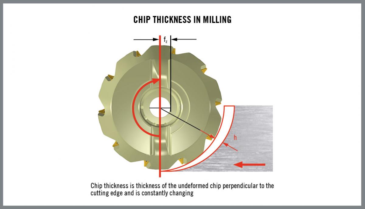
Basically, ‘chip thickness’ is the measurement of the thickness of the non-deformed material at a right angle to the cutting edge. Chip thickness correlates e.g. closely with the forces that affect the tool and workpiece. Excessively large chip thickness result in chipping and breakage of the cutting edge, while insufficient chip thickness causes rapid edge wear.
Determining and controlling chip thickness enables a manufacturer to maximise metal cutting productivity and efficiency, tailor cutting processes to specific workpiece materials and control costs. A lack of understanding of the importance of chip thickness leads many manufacturers to either overload or underutilise cutting tools, with negative effects on tool life and productivity.
With that said, there exists mathematical models that aid in understanding the functional significance of chip thickness. Chip thickness models have evolved from simple equations describing chips generated in steady-state turning operations to complex formulas that take into account numerous variables in the interrupted cutting environment of milling.
Chip thickness models for milling
In a continuous turning operation, chip thickness does not change. In milling, however, chips continually vary in thickness as the cutting edge intermittently enters and leaves the workpiece.
To simplify understanding of chip thickness in milling, approximately 40 years ago metal cutting researchers developed the concept of average chip thickness. The formula they produced mathematically creates a theoretical chip of a consistent average thickness. The average chip thickness model led to better understanding and control of the milling process.
When determining the average chip thickness, one has to take into account the cutter’s radial engagement with the workpiece, along with the cutting edge geometry, cutting edge angle and feed rate. Adjusting the feed rate enables a machinist to manipulate chip thickness.
The degree of radial engagement of the cutter in the workpiece may range from a small percentage of the cutter diameter up to 100 percent of the diameter in a slotting operation. Smaller radial engagement produces thinner chips. As the radial engagement grows, chip thickness reaches its maximum at 50 percent of cutter diameter. When radial engagement rises above 50 percent, chips begin to thin again.
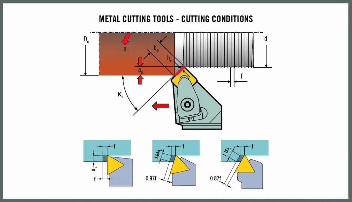
The preparation of the cutting edge also affects chip thickness. As a general rule, chip thickness must be at least as large as the radius of the cutting edge. For example, a 60 µm edge radius requires feed be adjusted to produce chip thickness of at least 60 µm. At a feed rate that is too low the edge will rub and fail to cut the workpiece material.
Milling tool cutting edges usually feature preparations that increase the edge radius to provide protection from chipping and breakage. Such preparations include hones, chamfers and T-lands. These preparations permit more aggressive feed rates when milling difficult materials or rough surfaces. The goal is to form the chip behind the cutting edge and thereby avoid concentrating pressure and impact where they will accelerate edge wear or breakage. Adjusting the feed rate moves the location of chip formation and controls chip thickness. Increasing feed rate creates a thicker chip and decreasing feed produces chips that are thinner.
The cutting edge angle has a direct effect on chip thickness. When the cutting edge angle is 90 degrees, as with a square shoulder cutter, chip thickness is 100 percent of the feed rate. But at a 45 degree cutting edge angle, chip thickness is 70 percent of the feed rate because the chip forms on a greater length of cutting edge. Reducing the cutting edge angle makes the chip thinner, and feed rate must be increased to maintain the desired chip thickness.
Application of the average chip thickness equation
The average chip thickness equation takes into account the tool’s cutting edge angle and the radial engagement of the cutter. Figure 3 graphs the equation’s application in side milling in blue and central milling in red. On the main graph, the radial engagement of the cutter is compared to the cutter’s diameter, expressed as the Ae/Dc ratio. The smaller graph in the corner of the figure plots the effect of the cutting edge cutting edge angle.

The figure illustrates a situation where the average chip thickness formula is not fully effective. When side milling with radial engagement that is very small compared to the diameter of the milling cutter, the formula does not function correctly (see dotted line). And in central milling, when 50 percent or more of the cutter is engaged in the cut, the red line shows continually increasing feed rate. That is contradictory to practical experience, where greater cutter engagement usually dictates feed rate reduction. Accordingly, the average chip thickness model is most useful when radial engagement is greater than 20 to 25 percent of the cutter diameter and smaller than 50 to 75 percent of that amount.
The average chip thickness model is based on geometric factors and simplifies a complex situation. Decades of application have shown that use of the average chip thickness model in tool life equations provides estimates that are accurate within plus or minus 15 percent. That level of accuracy is sufficient for power and torque calculations and for many operations in routine workpiece materials. Further, the time and effort for the calculations needed to manually solve the average chip thickness equation are reasonable.
However, when applications require a higher degree of accuracy or when milling involves so-called difficult-to-machine materials, a model that includes additional factors is needed.
Equivalent chip thickness
Swedish researcher Sören Hägglund developed a more global model that provides a measurement called equivalent chip thickness, which can produce tool life predictions with accuracies of plus or minus two percent. In the model shown in figure 4, the yellow arc represents the varying thicknesses of the actual chip as produced by the milling cutter. The orange bar, which illustrates the average chip thickness approach, is an unfurled version of the yellow chip. The blue bar represents equivalent chip thickness. A key difference is that the equivalent chip thickness model factors in the time the tool edge spends in the cut. That is significant because as the amount of the cutter engaged in the workpiece varies, the cutting edge spends a different length of time in the cut and the thickness of the chip that is generated changes as well.

The equivalent chip thickness model also takes into account the influence of the tool’s nose radius on chip thickness. The model employs a concept originally developed for turning operations by Swedish engineer Ragnar Woxén in the early 1930s. Woxén’s formula calculates theoretical chip thickness along the tool nose, essentially straightening out the nose radius and enabling the chip area to be described with a rectangle.

Chip thickness calculations help manufacturers avoid problems that arise when chips are thinner than a certain minimum or are thicker than a specific maximum level. When the radial engagement increases in relation to the cutter diameter, feed rate must be lowered to maintain the same chip thickness. This ensures that maximum chip thickness does not become excessive, a condition that will reduce tool life and eventually break the cutter.
On the other hand, producing chips thicker than a certain minimum is especially important when machining strain-hardening materials such as superalloys and titanium. A cutting edge producing chips that are too thin creates a work-hardened zone that is cut by subsequent cutting edges. Cutting the resulting layer of strain-hardened material accelerates tool wear and can shorten tool life by as much as a factor of three.
Many shops machine strain-hardening materials the same way as hardened steels, employing lighter depths of cut and lower feed rates. As a result, milling cutters often run at parameters that produce insufficient chip thicknesses, with poor results. The choice of conventional or climb milling techniques (see sidebar) also affects chip thickness and the machining of strain-hardening materials.
By: Patrick de Vos, Corporate Technical Education Manager, Seco Tools