
 iConnectHub
 Login/Register
 Supplier Login


Furthermore, Traditional Turning methods can cause adverse effects during the cutting process, such as heavy tool load, high and irregular cutting forces, vibration and poor chip control1. A key factor when high-speed machining these hard materials is main- taining a constant chip load, which remains vital when machining quality parts and prolonging tool life. In particular, if a chip load is too low or too high, that may cause the tool to wear faster causing many unwanted outcomes. These unwanted outcomes may include chips so large that they cannot get out of the cutter's way fast enough. For example, if a tool is cutting deep down in a slot the chips will have a hard time getting out of the way quick enough, which may cause the tool to break. Another adverse out- come of a low chip load is a rubbing effect, which prevents the machine from making clean chips, and will also heat up both the tool and the material, dras- tically reducing tool life. Therefore, maintaining a constant chip load is crucial in the manufacturing process
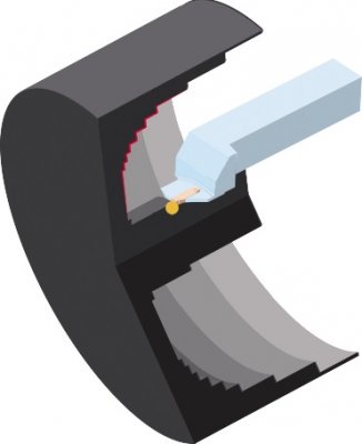
Figure 1 Traditional Plunge cutting methods create large engagement angles, irregular cutting forces, and uneven remaining materials.
See Sandvik Coromant Tips film: Grooving - trochoidal turning at
youtube.com/watch?v=sJnQnsz0cN8
ProfitTurning™ Capabilities
ESPRIT features a new and innovative lathe roughing strategy, ProfitTurning™ which helps eliminate the adverse effects of traditional turning methods. ProfitTurning™ is a high-speed cutting method added as an additional cutting strategy in ESPRIT’s existing Roughing and Grooving cycles. ProfitTurning™ is a productive and secure cutting method that enables manufacturers to make more efficient cuts with consistent chip loads and cutting forces, thereby reducing tool wear and decreasing cycle time. This is achieved using a toolpath algorithm based on an engagement control strategy, which allows for consistent cutting forces universally, and achieves the highest level of productivity.
Engagement control: Make reduced and constant engagements throughout the entire pass.
Another way to eliminate negative effects in traditional plunging is to maintain reduced and consistent tool engagement. ProfitTurning™ breaks the cutting surface into manageable pieces, and uses round inserts to roll in and out of the cut to control the engagement at both tool entry and exit. With smooth roll-in move- ments and a smaller feed rate, the cutting force at tool entry can be significantly reduced and maintained at a constant level. The feed rate is also maximized during these straight line movements called - parallel moves - maintaining constant engagement, and then reducing engagement when exiting the cut.
reduced fn max reduced fn max
fn max
Cut small, tricky areas with ease.
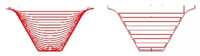
Not all cutting areas are as smooth and easy to reach, such as the one featured in Figure 3. Fortunately, ProfitTurning™ provides cutting strategies for all small and uneven areas. These areas are often defined by part profiles, roll-in/out arcs, and the minimum trochoidal radius. The minimum trochidal radius is deter- mined by users to limit the size of trochoidal moves in small corners where a cutting tool cannot easily fit. Another challenge in these difficult to reach areas is to keep constant tool engagement, so that the roll-in arc radius is not too large. To handle this challenge, ProfitTurning™ employs full trochoidal cutting inside these small areas until the tool reaches the “minimum trochoidal radius” as defined by the user. The mini- mum trochoidal radius then sets the size of the nonmachinable area at sharp corners, and the stepover is reduced to maintain constant tool engagement.
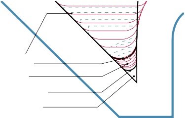
Regular Pass Area
Roll in-out Arc Radius
Trochoidal Passes
Minimum Trochoidal Radius
Unmachinable Sharp Area
Figure 3 The depth of cut of ProfitTurning™ toolpath in small areas progressively gets smaller
2See CAM Programming Tip: Trochoidal Turning Sandvik Coromant at youtube.com/watch?v=HRtSpY0Sdb
Alternate cut direction and smooth transitions
ProfitTurning™ allows users to alternate the direction of the cut to eliminate retract moves (Figure 4).
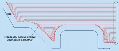
Figure 4 “Alternate Cut Direction” is activated and “Smooth Transitions” is inactivated
“Smooth Transition” replaces bridge moves in alternating toolpath with smooth arcs. Too large blend arc in corners can be replaced by this segment as well.
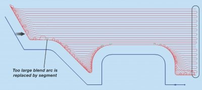
Figure 5 Both “Alternate Cut Direction” and “Smooth Transitions” are activated.
Benefits of ProfitTurning™
ProfitTurning™ uses round inserts or the full radius of groove tools to achieve higher feeds rates, in order to maintain a constant or near constant chip load. This is referred to as the chip thinning effect. In addition, Prof- itTurning™ reduces vibration and irregular cutting forces, which can result in poor surface finish and cutting tool damage by using round inserts with engagement control. In turn this makes ProfitTurning™ ideal for cutting hard materials and super alloys with thin walls, as displayed in Figure 6 and Figure 7 below.
In (Figure 6 below) half of the diameter of the insert, the feed rate per tooth and chip thickness are identical for a round insert. This is similar to a 90 degree cutter. As the lead angle of the cutter changes and depth of cut decreases (Figure 7), feed rate can be increased in order to maintain the proper chip thickness. Where depth of cut is lacking, users can make up for in an increased feed rate, which results in increased productivity3.
f=Feed Rate
h=Chip Thickness
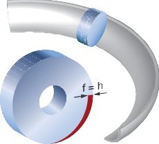
Figure 6 At half diameter of the round insert, feed rate per tooth is equal to chip thickness for a round insert3
f=Feed Rate
h=Chip Thickness
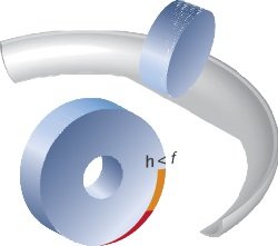
Figure 7 As the depth of cut decreases, the feed rate increases3.
3See Sandvik Coromant Tips film: lead/entering angle round inserts at youtube.com/watch?v=9CCr78Z60U4
Put to the Test!
Comparative testing of ESPRIT ProfitTurning™ was completed against conventional turning methods in collaboration with ESPRIT machine tool partners. The baseline for the test was established using a conven- tional ZigZag cutting strategy, and then compared to ESPRIT’s ProfitTurning™ strategy. The results were suc- cessful indicating a 25% reduction in cycle time using ProfitTurning™ as opposed to conventional cutting methods.
Another goal of the test cut was to evaluate tool life compared to traditional cutting strategies using ESPRIT ProfitTurning™. One part with two identical features was used in the test cut. One feature was cut with the traditional ZigZag technique and the other feature was cut with ProfitTurning™. During the test cut, TMAC4 (Tool Monitoring Adaptive Control) from Caron Engineering, was used to monitor the horsepower of the spindle. Caron Engineering has over 30 years of experience in monitoring and controlling CNC machines, and TMAC is just one of their products. TMAC operates on the principle that the power required to cut a part increases as the tool life decreases. With the support of TMAC, we measured the difference in horsepower between ProfitTurning™ and conventional ZigZag strategies. For each strategy, we started with an air cut, then measured the horsepower for each pass. That data was then averaged together to show the overall horsepower value for each groove.
In Figure 8, the orange bars display a gradual, yet consistent, 5% increase in horsepower between each groove, using the conventional ZigZag method. (Note: As the tool wears, the machine uses more horsepower to make the cut). This same data was collected for ProfitTurning™ – illustrated with the blue bars. When comparing the two cutting strategies the work over eight parts using ProfitTurning™ is 10.26%, while the work using the Conventional ZigZag method is 31.3%. The results shown by the graphs trendlines show that, by comparison to the conventional ZigZag method, users will experience a three times increased tool life, and tooling inserts will need to be replaced less often using ESPRIT’s ProfitTurning™.
Tool Work Difference Per Part
Sum of Profit Turning-10.26%
Sum of Convntional-31.3%
(3.047 times better better average wear over 8 parts)
Or by comparison of trendlines, ProfitTurning over 8 parts, wears 32% as fast as convntional
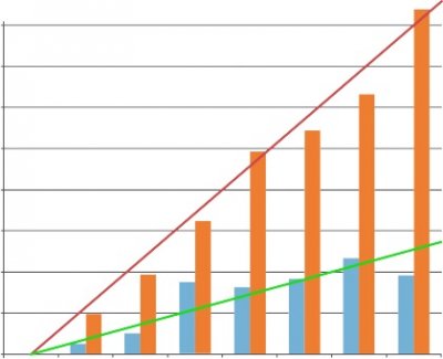

Figure 8 Tool work comparisons between ProfitTurning™ and the conventional ZigZag method
4TMAC, Tool Monitoring Adaptive Control, Caron Engineering is available at caroneng.com/
ProfitTurning™ Tool Selection
ProfitTurning™ uses round inserts or the full radius of groove tools. When using these round inserts, the entire cutting edge perimeter can be used when cutting, and the direction of the toolpath can be alternated to maximize the tool usage with higher efficiency, and to prolong tool life. Furthermore, round inserts can also tackle side loaded jobs, in which regular square inserts usually fail to accomplish. In addition, round inserts are suitable for materials with hardness levels of ISO-S and H5, such as heat-resistant superalloys.
In addition, when machining rigidity is also a factor when comparing round inserts to square inserts. Generally speaking, round inserts are more stout, making them the strongest inserts available, which also means they are less likely to produce harmonics during the cut, allowing for higher productivity. For example, Aerospace components are usually large, with increased radii and blending profiles designed to eliminate high stress points, which allows for round inserts to be used with ease.
Benefits of round inserts:
-The entire insert perimeter can be used when cutting
-The cutting direction can be alternated
-Effective engagement control with roll-in and out techniques
-Stronger cutting edge for tough materials
-Higher feed rates
-Side loaded cutting
ProfitTurning™ Applications
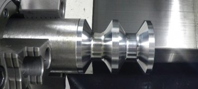
In Figure 9, an example of ProfitTurning™ applications is illustrated when deep grooving and profiling, where long slight tools are required. In the diagram disc and spool components are featured with deep cavities that need to be machined from a solid or finished after welding. When machining these typical components there is a high tendency toward vibration with a huge depth to width ratio. By adopting ProfitTurning™ users can optimize these difficult machining applications with maximum rigidity and minimized vibration allowing for increase productivity. Additional examples of ProfitTurning™ applications are featured in Figure 106.
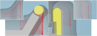
Figure 9 An example of ProfitTurning™ applications – deep grooving
5See Negative basic shape inserts in Sandvik Coromant – Turning tools 2012, available at
sandvik.coromant.com/sitecollectiondocuments/downloads/global/catalogues/en-gb/turning/turn_a.pdf
6See Engineered solutions for the aerospace industry in Sandvik Coromant - Application Guide – Heat resistant super alloys.pdf, available at
sandvik.coromant.com/sitecollectiondocuments/downloads/global/technical%20guides/en-us/c-2920-034.pdf
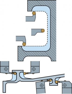
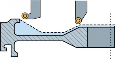
Figure 10 Some more examples of ProfitTurning™6
Test Results
The first test cuts were made at the Mazak Technology Center in Gardena, California. The goal of this first test cut was to verify that the original toolpath motion worked properly with the proper feeds/speeds. The results showed that both the OD groove/contour and face groove were machined with the “alternate” parameter turned on when cutting the face groove. The OD cutting conditions and final results proved successful, and the surface finish was consistent with a high speed roughing cycle.
EXAMPLE 1
Location Mazak Technology Center, Gardena, California, USA
Part 316 Stainless, Annealed (6” Diameter, ~149 Brinell)
Machine Tool Mazak Quick Turn Nexus 200 II
Control Mazatrol Matrix Nexus 2
Cutting Tool Insert Sandvik N123L2-0800-RO 1125
Cutter Diameter (in) 0.315
Tool Motion Pattern ProfitTurning™
Spindle Speed, CSS 800
Feed Rate, IPR 0.032
Depth of Cut (in, %) 0.025, 7
Roll In/Out Radius (in, %) 0.394, 125
Alternate No/Yes
Coolant Yes
Video Link
Images
Example 2
Location Okuma Partners in THINC facility, Charlotte, NC
Part D2 Tool Steel annealed, ~23 HRC 2.5" OD x ~36" OL
Machine Tool Okuma Genos L300
Control
Cutting Tool Insert ISCAR GDMY 840 IC 808
Cutter Diameter (in) 0.315
Tool Motion Pattern ProfitTurning™
Spindle Speed, CSS 550
Feed Rate, IPR 0.05
Depth of Cut (in, %) 0.04, 13
Roll In/Out Radius (in, %) 0.394, 125
Alternate No/Yes
Coolant Yes
Video Link youtube.com/watch?v=GP4ft3rjqcw
Images
Results
Cycle Time: 22 seconds with ProfitTurning™ resulting in a time savings of 19 seconds down from 41 seconds required with conventional turning.
Equations of Business
In today’s manufacturing world a lot of money is spent on adopting and investing in new technologies. However, there still remains a decision on when to adopt those new technologies versus continuing to use traditional methods. Adopting ESPRIT’s ProfitTurning™ can increase cutting speeds and decrease cutting time, but what is the investment cost to use this new technology compared to traditional methods? We used a Sandvik Turning calculator to show users just that by setting priorities when choosing a cutting strategy. We calculated the cost per part using ESPRIT ProfitTurning™ and round inserts (Table 1), and in parallel used a similar cost evaluation using the traditional ZigZag cutting method (Table 2) with the same round tool insert and holder. The final results showed that the unit price to cut one part using ProfitTurning™ costs 60% less than the unit price of using the traditional ZigZag cutting method.

COST PER PART
Data for Equations of Business
Number of Parts Per Year-5,000
Machine cost per hour ($)-$50
Total cycle time per part(s)-22
Insert Cost ($)-$45
Insert tool life (# of parts)-24
Edges per insert-2
Insert per tool-1
Tool holder cost per part-$150
Max insert indexes-1
Machine cost per part ($)-$7.49
Total cost per year ($/year)-$37,465
Cost evaluation using ProfitTurning™
Number of Parts Per Year-5,000
Machine cost per hour ($)-$50
Total cycle time per part(s)-41
Insert Cost ($)-$45
Insert tool life (# of parts)-8
Edges per insert-2
Insert per tool-1
Tool holder cost per part-$150
Max insert indexes-1
Machine cost per part ($)-$22.13
Total cost per year ($/year)-$110,660
Cost evaluation using traditional ZigZag cutting method
6The Sandvik Coromant Turning Calculator is available at
sandvik.coromant.com/en-gb/knowledge/calculators_and_software/apps_for_download/Pages/turning-calculator.aspx
Conclusion
The ProfitTurning™ cutting strategy in ESPRIT features a toolpath that maintains consistent chip load and cutting forces, allowing cutting speeds to be significantly increased. By employing controlled engagement techniques using round inserts, the ProfitTurning™ toolpath also reduces vibration and residual stresses, making it particularly useful for thin walls or hard materials, such as superalloys. This innovative cutting strategy results in significantly reduced machine cycle time and cost per part, allowing for increased productivity and making it the ultimate turning solution.
Jordan Shoes


