
 iConnectHub
 Login/Register
 Supplier Login


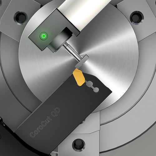
As a practical consideration, it should be noted that the cutting edge is 7 mm (0.276 inch) above the Y = 0 position when mounted on a standard blade adaptor. The operator should make sure that this protrusion is offset in the CNC program.
Markets call for shorter lead times and reduced inventories, and this creates a clear incentive for OEMs and perhaps even more so for their suppliers to look for ways to streamline component production as much as possible. Complex geometries must be accomplished with a minimal number of set-ups and operations, preferably in a single machine. Profitability of a given part may even depend on the capability of combining several set-ups in a single machine.
Machine tools upgraded with live tooling and Y-axis
One aspect of the single set-up trend is adding ‘live tooling’, in other word rotating tools, to turning centres. To accomplish this, Y-axis turn-mill machines were introduced in the late 1990s. The initial idea was to simply make it possible to drive a milling cutter, drill or threading tap on one or more tool positions in the turret to eliminate limitations of polar interpolation and the related programming difficulties.
The first simple types of live tools in turning centres had a significant limitation, however. Because the rotating cutters were in most machine designs simply added to the turret, they could only be driven in the same two axes of motion as the turning tools, in other words on the X- and Z-axes. As a result of this, any workpiece feature that is not parallel or perpendicular to the spindle centre line or is located along the workpiece centre line, was not within the direct reach of the rotating drill, mill or tap driven by the turret.
To improve the reach, an extra set of ways was added to move the live tool across the spindle face. This was accomplished by mounting the live tools on revolver sides or on its face, by installing the Y-axis ways on a slanted bed, or by using an independent milling head.
Both machine tool makers and manufacturers soon recognized the benefits of this approach. Now, around two decades later, the Y-axis has become a standard feature in nearly all multi-task machines and optional in many new turning centres. Adding the Y-axis into a turning centre provides 90-degrees angularity between the three linear axes, in a way much like a 3-axis machining centre. As the Z-axis customarily is parallel to the spindle centreline in most lathe-type machine tools. While the X-axis provides the conventional plunge turning feed motion, the Y-axis creates a vertical dimension perpendicular to the plane jointly defined by the Z- and X-axes.
Challenges when parting off
Parting off is a crucial stage in any turning process where it is required? It takes up only a small percentage of the total cutting time but it is usually the last operation before the part is finished. A breakage of the parting tool can easily result in machine downtime and quality issues, and in a worst-case scenario the workpiece may have to be scrapped and all the value added during previous work stages is lost. Due to this, manufacturers are reluctant to compromise in any way the process security of a parting operation.
Material cost is another major factor. Particularly when working costly materials, such as heat- resistant super-alloys (HRSA), there is a strong incentive to use the narrowest possible inserts.
These factors result in two diametrically opposite requirements for parting tools: They should be as narrow and slender as possible to minimize the loss of material and to optimize the reach of the tool for maximal work diameters. Yet slender tools easily suffer from poor stability and consequently from vibrations and noise. Surface finish and dimensional tolerances ruined by chattering are generally unacceptable risks in parting operations.
Y-axis parting
While the Y-axis substantially broadened the possibilities to use rotating tools in multi-task machines and turning centres, now this capability has inspired a major innovation in one of the original missions of these machine tool types: Y-axis parting. This new parting-off tool and method offer significant productivity and process security improvements in potentially any parting operation.
The innovation from Sandvik Coromant, Y-axis parting, is based on an incredulously simple principle. While conventional parting off tools align with the X-axis of the machine tool, the Y-axis tool has simply been rotated 90° anti-clockwise to align with the Y-axis.
In the conventional parting tool configuration, the relatively long and slender cutting blade and holder is fed at a 90° angle into the rotating workpiece and the largest cutting force is generated by the cutting speed, and the rest by feed motion. The resultant force vector is directed diagonally into the tool at an angle of roughly 30°, in other words across its second weakest section (only the width of the blade is weaker). This is conventionally counteracted by reducing the blade overhang and by increasing the blade height. The downside of both remedies is potentially compromised usability of the tool.
By turning the tip seat 90 degrees and utilizing the Y-axis, the tool can cut its way into the workpiece essentially with its front end, which nearly aligns the resulting cutting force vector with the longitudinal axis of the blade.
The FEM1 analyses carried out by the Sandvik Coromant R&D team confirmed that the more favourable distribution of forces eliminates critical stresses typical to conventional blades and increases the bending stiffness at a maximum cutting depth (CDX) of 60 mm (2.36 inch) by more than six times. Or, conversely, the susceptibility to plastic deformations and instability is as low as one sixth in the Y-axis design compared with the deformations typical to conventional parting blades.
Benefits of Y-axis parting
The more than 600% increase in blade stiffness allows substantially higher feed rates and longer overhangs without a loss in stability, which consequently improves the productivity of the tool in equal measure. Thanks to this, parts can be parted off closer to the subspindle to save raw material and improve the stability of the operation. Rather than the rigidity of the parting blade and tool holder, it is the insert that now represents the bottleneck for increasing performance of parting operations.
The general recommendation for parting off bars is to minimize overhang (OH) or, at a long OH, to use a light cutting geometry or to reduce feed. A common threshold value for reduced feed is an OH exceeding 1.5 times blade height. With Y-axis tooling, longer overhangs can be achieved without settling for less than optimal feed rates, cutting geometries or tool dimensions.
As in all turning operations, it is important to position the cutting edge of a parting tool as close to the workpiece centre line as possible to avoid pip formation or tool breakage. Parting tools should be set within ±0.1 mm (±0.004 inch) of the workpiece centreline. The conventional recommendation for long overhangs is to set the cutting edge 0.1 mm (0.004 inch) above centre to compensate for bending down. Thanks to the increased stiffness and consequently reduced bending, Y-axis tooling may eliminate the need for over-centre settings and prevent the related disadvantages such as premature insert breakages when pushing through centre and rapid flank wear.
Measuring the tool length calls for particular care, because when it comes to Y-axis tools the length also determines the centre height. On the other hand, this can be seen as a security feature against set-up errors: because measuring the length is always necessary, it also serves as a double-check for the centre height setting. If the cutting edge is difficult to see, there is also a gauge plane on the end of the tool. The distance between the gauge plane and the cutting edge is marked on the Y-axis tools.
Other benefits include lower noise levels, better surface finish and a more reliable process as well as the capability to part off larger diameters than currently possible.
Machine-specific aspects of Y-axis parting
Turning centres are generally used for mass production from bar stock, typically 65 mm (2.56 inch) in diameter, and in this type of machining the biggest benefits of Y-axis parting are improved productivity and surface quality. The opportunities for quality optimization can also be interesting, since parting off is typically the last stage for a component. An additional opportunity is to improve the machining economics by reducing the parting width.
For multi-task machines, Y-axis parting blades primarily offers increased accessibility and capability for larger diameters. A pre-test confirmed a 50% increase in the overhang when cutting a conventional 120-mm diameter bar at the maximum feed capacity of the insert. A 300% productivity increase was achieved with no process security complications. In a customer test case, Y-axis parting successfully replaced band sawing for a 180-mm diameter Inconel bar, resulting in significant productivity improvement thanks to dramatically shorter machining times.
In a typical slant-bed machine, the X-axis creates an ‘uphill’ slanted towards the front of the machine, with spindles on one or both side ends of the slant bed, and the X-axis travel is usually substantially longer than the Y-axis travel. The resulting work space limitations must be considered when considering the usability of Y-axis parting for a specific component.
In a multi-task machine, which essentially could be characterized as a machining centre with turning option, typical tool assemblies, such as Coromant Capto® C6 or HSK63T blade adaptor, are often relatively long to enable sufficient reach between the main chuck and sub-chuck. As a result of this, the total set-up is weak in the X direction compared to the Y-axis load, where the cutting force is directed into the tool assembly and into the machine spindle.
Similar conditions apply to many turning centres equipped with a driven tool/milling option on the Y-axis. Typical Y-axis tool assemblies, usually based on a VDI adaptor or a bolt-on blade adaptor for the machine-adapted clamping unit (MACU), are long and slender to reach between main- and sub-chuck and allow parting off close to chuck. Again, the result is a weak set-up in the X-direction compared to Y-axis, where the cutting force is directed into the tool assembly and into the turret. Y-axis parting can help to eliminate both problems.
How to get started
An investment in Y-axis parting is first and foremost a change in the approach to parting operations and the related ways of working. It offers a way to more fully utilize the capabilities of machines already fitted with a Y-axis. Alternatively, it is an option that can substantially increase the productivity of parting operations in a new machine or a modified process set-up. The biggest concrete investment is in programming, with obvious implications in terms of personnel resources and scheduling. The tool motion itself is easily programmed, while different machines and control system have different parameter settings that must be changed to get constant cutting speed on the Y-axis. Necessary parameter settings are described in the CNC control manual.
Y-axis parting can even offer a chance to reduce the tool inventory because there is less need for dedicated blades and since the new Y-axis blades fit in standard adaptors and use standard CoroCut® QD inserts.
Lebron XIII Low EP


