
 Login/Register
 Supplier Login


Getting a servomotor-based injection molding machine is only a first step in energy saving. As injection parameters also affect energy consumption, the next step is to optimize them with the help of a high-resolution power meter that can give a result up to 3 significant figures in 10 shots. Even better, the energy consumed by each heater zone is analyzed. An intelligent power meter iPM integrates a digital power meter with a computer to accomplish this task. It can compare the energy consumption of different drives, different heating technologies, and different insulation covers.
Energy and power have different units but in English they are used interchangeably.
iPM
An iPM connects a digital power meter with a 0.0001 kWh resolution to a computer though Modbus RTU. Two screens control and display the energy consumption results which could be recorded in a USB drive or displayed on a PC or Smartphone connected to iPM by Wi-Fi or RJ45 cable. The high resolution enables useful results in a few minutes.
Meter 1 screen
The Meter 1 screen controls and measures energy consumption in integral number of cycles. See the orange box in Fig. 1.
Once the Stop mode is selected, press the Clear button Clear btn to clear the screen and then the Start button Str btn to start the recording at the next mould close.
Each cycle recorded has a Seq #, a start time Real tm, cycle time Cyc tm, cycle energy consumed Cyc engy and heater energy consumed Ht engy. Heat % is the ratio Ht engy / Cyc engy.
Fig. 1 shows the result testing a small machine at 23 tons of clamping force and 25 mm diameter screw. The energy consumption is 0.0079 kWh per cycle of which 34% is heater energy. Three other metrics of energy consumption at the bottom of the screen are:
- kWh/h at 2.987 kWh/h. This figure is affected by cycle time.
- kWh/50 shots at 0.3970 kWh, as the kWh per shot is too small.
- kWh/kg of processed material at 0.4411 kWh/kg. The operator has to fill in Shot wt. first.
The digital meter readings are displayed in the red box on the right side of the screen. Machine energy M/c engy starts accumulating when Str btn turns from OFF to ON.
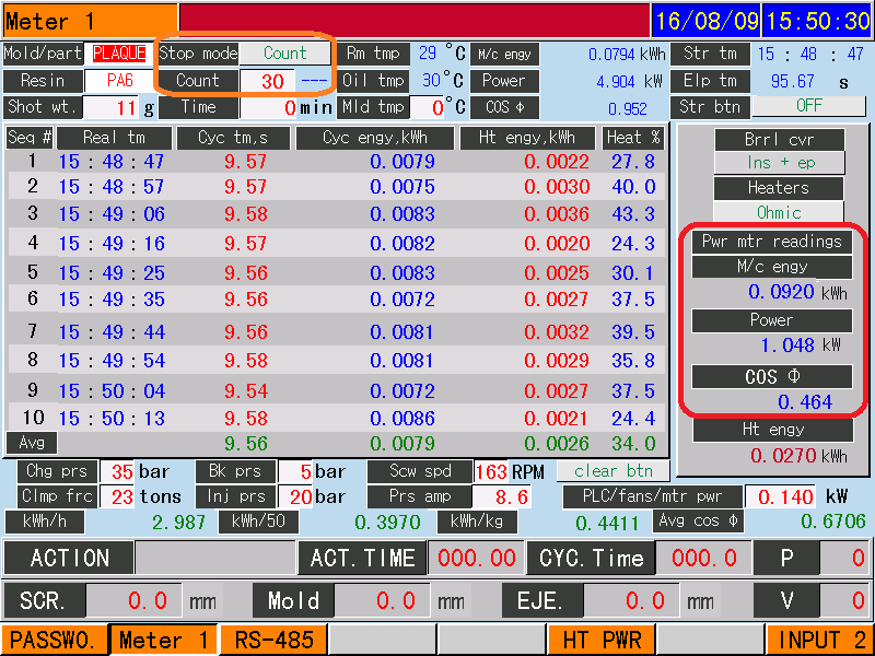
Fig. 1. Meter 1 screen
The heater energy Ht engy below the red box comes from the Heater Power screen.
Heater Power screen
Heater Power screen displays the heater power per zone for nozzle (N) and up to 6 barrel zones. The operator first fills in the nominal heater power of each zone * 0.9 as heat power drops after heating up.
The computer accumulates the ON time per zone and divide it by elapsed time Time to get ON %. Fig. 1 shows zone 4 has the highest ON % due to its proximity to the water collar. As a result, zone 3 does not need to turn on at all. N has the next highest ON % due to its contact with the cold mould. Furthermore, the nozzle heater has no insulation.
The energy consumed per zone is displayed in Energy c. The total energy consumed for all zones is displayed in Total energy c. Fig. 2 shows zone 4 consumed 0.9593/1.4551 = 66% of Total energy c.
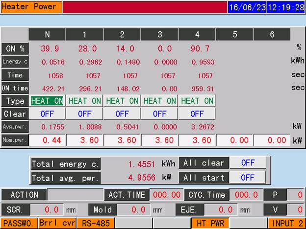
Fig. 2. Heater power screen
End zone temperature setting
In Fig. 2, zone 4 is the end zone. As the last calculation shows, the heater energy consumed by the end zone dominates the heater energy consumed.
We varied the set temperature of the end zone to see its effect on heater energy consumed. Zone 4 is set at 180°C, 215°C, 250°C (which are 35°C apart) and all the other zones at 250°C.
In Fig. 3, the ON % of zone 4 at 215°C is in the middle of those at 250°C and 180°C, so end zone ON % is directly proportional to end zone set temperature. The high zone 4 set temperature at 250°C has reduced the ON % of zone 3 but the total heater energy is still the highest at 250°C (see Tbl. 1). We can also calculate that heater energy is directly proportional to end zone set temperature.
As machine energy consumption = electric motor energy consumption + heater energy consumption, electric motor energy consumption would increase as screw torque need to increase at lower end zone temperature. From Tbl. 1 we see that at 180°C the machine energy saved is less than linearly predicted by 13% (6.5% * 2). The reason the machine energy saved is less than the heater energy saved at 26% is heater energy is a fraction (34% in Fig. 1) of the machine energy, depending on the end zone set temperature. Such a high fraction implies we could do energy saving at the heaters. One way is to remove the last heater band of the barrel to increase the distance of the remaining heater band from the water collar to reduce heat loss by conduction. See Fig. 4.
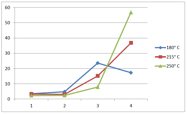
Fig.3. ON % of the four zones t different end zone set temperatures
|
End zone set temp. |
180 °C |
215 °C |
250 °C |
|
Heater energy, kWh |
0.1487 |
0.1732 |
0.2009 |
|
Heater energy saved |
26% |
13.8% |
0% |
|
M/c energy, kWh/kg |
0.3713 |
0.3861 |
0.4131 |
|
M/c energy saved |
10.1% |
6.5% |
0% |
Tbl 1. Machine energy in kWh/kg and energy saved
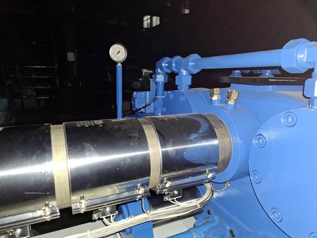
Fig. 4. End zone heaters and water collar
Fast or slow charge speed
In an injection moulding cycle, charge and cooling take place at the same time. As long as charge can be finished within the cooling time, charge speed has no effect on cycle time. On a servo driven injectiong moulding machine, we studied ON % and machine energy consumed for charge speeds at 17%, 60% and 100%.
At 100% charge speed, there is more frictional heating and therefore has a lower ON % than at 60% charge speed, for all zones. See Fig. 5.
As for machine energy consumed, when reduced to 60% charge speed, the saving is 14.4%; when reduced to 17%, the saving is 18.4%. See Tbl. 2.
These tests were done at 215°C end zone temperature. If end zone temperature is reduced to 180°C, a saving of 20% could be reached.
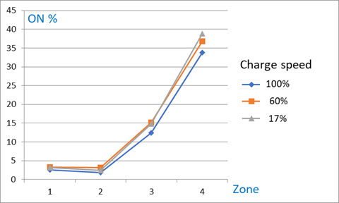
Fig. 5. Zone ON % at different charge speeds
|
Charge speed |
17% |
60% |
100% |
|
M/c energy, kWh/kg |
0.3682 |
0.3861 |
0.4512 |
|
M/c energy saved |
18.4% |
14.4% |
0% |
Tbl. 2. Machine energy kWh/kg and energy saved
Heating technologies
Three barrel heating technologies are available on the market: the more conventional resistive (Fig. 4), infrared and induction (Fig. 5). Are the more modern technologies more energy saving? We can use the Heater Power screen to find out.
The heat from a resistive heater has to go through the rusty contact heat resistance between the heater and the barrel surface. Infrared heating uses radiation to transfer heat to the barrel surface so the contact resistance is irrelevant. Inductive heating makes use of the hysteresis property of barrel material when reverse magnetized by high frequency alternating current.
The energy saving of infrared heating is not significant. Energy saving is not related to heater technology, but to barrel heat loss. As heat is generated inside the barrel in induction heating (unlike the other two technologies), theoretically the heat loss is reduced.
Barrel insulation cover plays an important part in reducing heat loss.
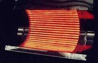
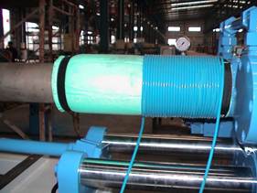
Fig. 6. Infrared and induction heating technologies
Insulation covers
Heat from barrel is lost through convection, radiation and conduction. The purpose of insulation cover is to reduce cover surface temperature in order to reduce convection and radiation losses. The heat loss to water collar is by conduction. Perforated insulation cover does not reduce much convection loss.
The formulae of the three heat losses are well-known. Heat loss by convection is q = h A (Tw – To), in which A is the cover surface area, Tw is surface temperature, To is room temperature, h is figured out by empirical formulae.
Heat loss by conduction is q = k A DT / L in which k the conductivity of the barrel material, A is the cross-section area of the barrel, DT is the temperature difference between two points, L is the distance between the two points as the length of the arrow in Fig. 4. The higher is L, the lower is q.
iPM could measure heat consumption but not heat loss. When there is no motion (not even charge), heat consumption to keep the zones at constant temperatures is heat loss. The heat losses from formulae turned out to be 70% of the measured heat consumption. The reasons are the insulation cover does not cover all the zone 1 heaters (Fig. 7), it does not surround the barrel completely but leaves a gap for the heater and thermocouple wires below, it does not have one temperature but temperatures higher at the top, lower on the sides and no surface at the bottom.
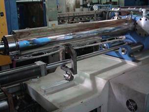
Fig. 7. Dual-layer stainless steel and epoxy barrel covers
Conclusion
The high resolution of the power meter allows parameters to be optimized with an energy saving up to 20%.
Servomotor only reduces energy consumption of motions but not that of heaters. Total heater energy is directly proportional to end zone set temperature.
The Heater Power screen measures only heater energy and could be used to distinguish between heater technologies and insulation covers more accurately.
Many other energy saving issues have been investigated. For asynchronous motor, fast charge is more energy saving than slow charge, a more powerful motor is more energy saving as it heats up less, a low displacement (of a dual-displacement pump) for slow motion like holding pressure saves much energy as the motor heats up less. We have also found the power factor of a servomotor is much lower than when it is fully loaded.
How different materials and different wall thicknesses affect Heat % is an academically interesting question. iPM can give you the answers.
To view the video of Tat Ming's technology in action, click here.
For more information, contact:
