
 Login/Register
 Supplier Login


Therefore recent advancements have made robotic automation in this segment far more viable.
In principle the addition of sensors to robotic equipment will enable the automation technology to operate with remarkably human-like capabilities. When a sensor system is correctly selected, installed and trained (programmed) it will significantly extend the operational capability of the robotic arm and controller combination. In robotic welding systems the introduction of sensors provides the adaptive capability of touch and sight to address the challenges of a “moving” weld seam or component.
Historically the use of sensors with the ability to solve the problems of the moving target was not feasible for general industrial (non-automotive) type companies. The typical prohibiting factors were one or more of the following: the high initial investment costs; extended processing times; the physical size of the sensor equipment; the inability to achieve the desired accuracy of process; and the “stack-up” of tolerances that traditionally have precluded automated welding.
In welding applications recent and ongoing advances in sensor technology are enabling previously prohibited joint tolerances and configurations to be effectively produced with acceptable quality and weld integrity. Moreover, the technology has become performance and cost competitive for general industrial organisations, not just for the large dollar automotive and tier-one manufacturers.
There are three challenging phases of the welding process where the introduction of sensors has enabled the use of robotic automation in the welding of inconsistent joints:
· Joint Edge Detection - finding the edge or start of a weld seam. A number of media have been successfully developed that effectively resolve this process demand. They generally differ in accuracy, speed of acquisition, complexity and cost.
· Joint Seam Tracking - maintaining the desired weld path. In some instances the start or edge of the joint may be relatively simple to control within the tooling or fixturing. The seam itself, however, may vary due to manufacturing methodology or thermal influences of the process. Tracking of the seam by various methods can overcome this shortcoming of manufactured parts. This offers another opportunity to automate the welding of previously prohibited joints and components.
· Measuring the width or profile of a joint. This helps in two ways: 1) decisions can be made to influence the robot path and speed within the joint, and 2) the process itself can be adapted to suit the local varying conditions.
While there are a number of factors that influence the quality of a welded joint, the major sensing media capable of measuring joint width and geometry deviation have developed considerably over the last few years, greatly increasing their reliability and performance.
Joint edge detection
In determining the start of a joint or the edge of a plate, the primary sensor tools now available to the manufacturing industry are Tactile Sensing and a Proximity Sensor.
Tactile sensing
The tactile sensing solution is well established. In principle it is a voltage applied to the welding gas nozzle, welding wire or independent probe. The prominent welding power source manufacturers all have their versions with some variations. The controller of most mainstream robotic welding systems is also able to provide this functionality. The applied voltage can differ from as low 42Vdc to whatever is legal and considered safe in the specific region of use. The monitoring or sensing for measurement can be as low as 7Vdc. Generally the higher the output voltage the more reliable the signal, with such things as corrosion and mill scale being the main influencers.
The principle of operation for a tactile sensing system is for the voltage to short out as it makes contact on the component via either the wire, gas nozzle or an independent probe. An example of this type of sensor is SmarTac from ABB.
The short circuit is recognised by the either the robot controller or welding power source, and resulting programming decisions are then made.
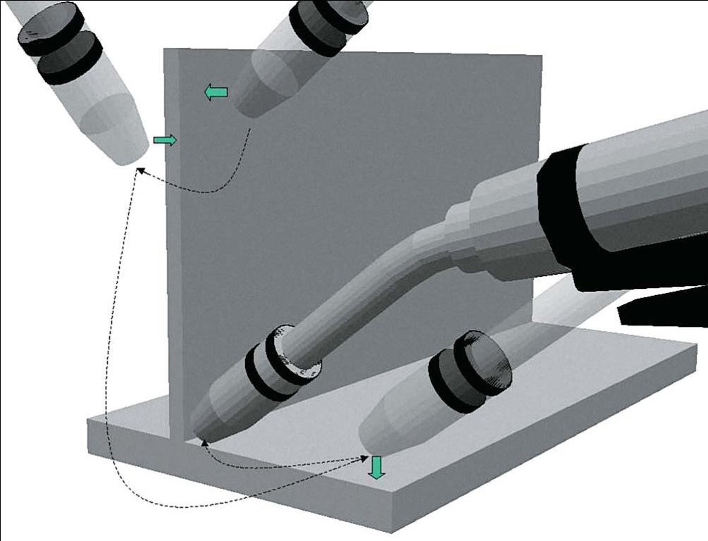
An illustrative example is of a bridge deck plate being welded to a supporting ‘I’ beam. The ‘I’ beam is within its manufacturing tolerances but it varies in height in excess of the weld tolerance. So a simple touch down in the Z plane enables the height to be established. Two additional touch downs in the X and Y plane allow the robot controller to deduce the corner of the plate for the start of the weld. Tactile searches like this take between 2 to 4 seconds depending on the size of the search zone (definable) and the approach speed of search.
Proximity sensor
The simple proximity sensor has existed for a number of years but recently the performance and reliability has become far more dependable. The sensor approach works in a similar manner as the tactile sensing system, providing an interrupt for the robot controller to make decisions. The proximity sensor, however, is non-contact and operates using an analogue inductive field. The advantage of this approach lies in the innovative skill of the robot programmer. A well conceived, strategic route of the robot traveling over the component will provide benefits of reduced sensing time and more reliable data received.
The Proximity Sensor is attached adjacent to the welding torch, while not compromising the desired welding torch approach angles when in operation. The robot travels over the parts and edges to be found, and any signal changes or interrupts are monitored and acted upon by the robot controller. The speed of travel and level of sensitivity are a derivative of the chosen sensor. Multiple readings from the sensor can be combined with logical instructions, providing simple X, Y and Z information, as well as angular and rotational data. The “interrupt” data can be used in number of ways, including: Defining a position in space to execute a weld; Offsetting a weld seam that varies from batch to batch; defining a specific product to be welded automatically given a strategic search; calling a number of routines which may used for flexible manufacturing; and confirming a product has been loaded correctly
With the edge or start of weld now defined by one of the previous methods the challenge now falls into two areas. Firstly it is important for the arc to remain in the correct relationship to the weld joint as it travels along the path so that weld integrity is maintained. Secondly should the weld joint change in size or geometry the process needs to be able to adapt to the local conditions to avoid a reduction in quality or worse still the potential of weld failure.
Joint seam tracking by vision and laser
The use of vision and lasers to track and modify the welding criteria on the fly are now established and proven technologies. This section provides insight into some of the considerations that need to be addressed before utilising these processes for seam tracking. The initial and most primary consideration is that vision and laser systems are high performance options that demand a higher skill set and level of complexity than most other methods.
There are three main methodologies that can facilitate seam tracking, each providing varying levels of investment, complexity and capability. They are: vision solutions, laser scanning, and through the arc sensors. Other solutions such as ultrasonics exist but are not yet prevalent in mainstream automation and are not considered within this document.
Historically most of the vision applications have been employed in situations where the requirements of quality were uncompromising, often with significant safety implications.
A relevant example is the railroad industry producing undercarriage bogies for passenger carriages. The build-up of these types of structures use large thick plate fabrications, forgings and castings. Such products have industry guarantee requirements of 30 years or more. The plates, castings and forgings when assembled inherently have tolerances in excess of the desired welding criteria. The introduction of a high end vision tracking solution enables these joint types to be produced with excellent results. This environment is clearly one where the higher cost threshold for such tools is much more acceptable.
Today there are more, lower cost and capable solutions available. It is important, however, to consider each system on its own merit, as not all vision/laser solutions offer the same capabilities. Without proper planning and preparation it becomes a risk that the selected process or system can either become compromised, or is incapable of performing the anticipated or desired tasks for which it was purchased.
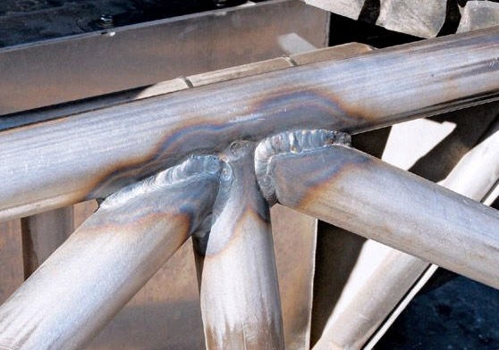
Fig 1: Example of tube joints exhibiting multiple tolerance stack-up.
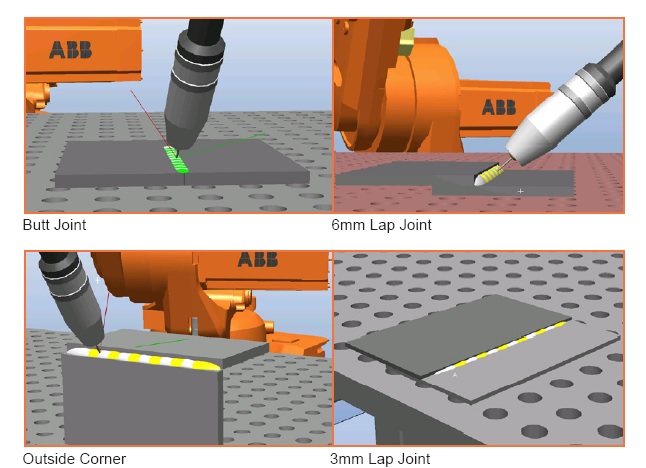
Examples of joint types more readily produced with enhanced sensors.
Source: ABB
Click to view E-zine:International Metalworking News for Asia – Dec issue
Air Jordan VII 7.5 Ture Flight